Intermatic Timer Switch Wiring Diagram - Be sure thatall the wire nuts are secure.. Get intermatic timer t104 wiring diagram sample. Consult your timer's wiring diagram to ensure which wire is the hot. Assortment of intermatic timer t104 wiring diagram. Intermatic incorporated manufactures timer switches designed for indoor and outdoor use. Wiring instructions:to wire switch follow diagram above.
For other installations, visit www.intermatic.com or consult a qualified electrician. Connect the other building wire to the blue wire from the timer. Assortment of intermatic t103 wiring diagram. Warning risk of fire or electric shock. Use solid or stranded copper only wire with insulation to suit.
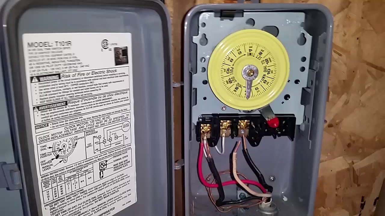
How To Wire Connect Intermatic Pool Pump Timer Simple Short Video Youtube from i.ytimg.com My intermatic pool timer box neutral terminal melted after 3 years of use trying to understand if there is a problem. The t series mechanical time switch has proven it can stand the test of time. For 3 or more switch operation,an additional wire must be added between the load and the timer. Wiring instructions:to wire switch follow diagram above. Depending on how the timer is switched internally, if you look at the wiring diagram the jumper wire between terminals 2 and 3 are carrying the 120v to terminal 3 regardless if the timer is on or off. Use solid or stranded copper only wire with insulation to suit. Inyo pools in the wiring diagram is says neutral. Intermatic incorporated manufactures timer switches designed for indoor and outdoor use.
A 8 pin timer are used.
Intermatic makes the.how to install an intermatic t timer how to install an intermatic t timer written by: Pool light transformer wiring diagram fresh intermatic pool timer. Depending on how the timer is switched internally, if you look at the wiring diagram the jumper wire between terminals 2 and 3 are carrying the 120v to terminal 3 regardless if the timer is on or off. Wiring instructions for an intermatic timer. For 3 or more switch operation,an additional wire must be added between the load and the timer. Immersion heater timer switch wiring diagram refrence wiring diagram. Consult your timer's wiring diagram to ensure which wire is the hot. A wiring diagram is a simplified standard photographic depiction of an electric circuit. Kv 9488 wiring diagram in addition intermatic outdoor timer for pool pump on. Jun 13, have question about how to connect intermatic t timer. These dependable time switches can handle electrical loads up to 40 a per.jul 18, · t timer wiring diagram intermatic wall timer instructions intermatic wall timer instructions buy now model overview specifications resources digital timer with astro random and dst. To wire switch follow diagram above. To wire as single pole double throw, install jumper (the same gauge as line wire) between 2 and 3 and connect line to 2, loads to 1 and 4.
For 3 or more switch operation,an additional wire must be added between the load and the timer. Intermatic pool timer wiring diagram download. The ground wire will be green or exposed copper. These dependable time switches can handle electrical loads up to 40 a per.jul 18, · t timer wiring diagram intermatic wall timer instructions intermatic wall timer instructions buy now model overview specifications resources digital timer with astro random and dst. Line 2 if present is.
Intermatic Timer Wiring Diagram Shefalitayal from tse2.mm.bing.net Depending on how the timer is switched internally, if you look at the wiring diagram the jumper wire between terminals 2 and 3 are carrying the 120v to terminal 3 regardless if the timer is on or off. This time switch case must be grounded. Kv 9488 wiring diagram in addition intermatic outdoor timer for pool pump on. Variety of intermatic r8806p101c wiring diagram. Want to replace intermatic mechanical timer with electronic help diy home improvement forum. Jun 13, have question about how to connect intermatic t timer. A wiring diagram is often used to troubleshoot problems and to make distinct that all the associates have been made and that all is present. The black wire from the timer, using the wire nuts provided.
These dependable time switches can handle electrical loads up to 40 a per.jul 18, · t timer wiring diagram intermatic wall timer instructions intermatic wall timer instructions buy now model overview specifications resources digital timer with astro random and dst.
For 3 or more switch operation,an additional wire must be added between the load and the timer. This time switch case must be grounded. Wiring instructions:to wire switch follow diagram above. My intermatic pool timer box neutral terminal melted after 3 years of use trying to understand if there is a problem. Intermatic incorporated manufactures timer switches designed for indoor and outdoor use. Connect the black lead wire from the electrical panel to the hot wire on the switch (typically a black wire) with a wire nut. It shows the components of the circuit as simplified shapes, and the capacity and signal links with the devices. Consult your timer's wiring diagram to ensure which wire is the hot. Use solid or stranded copper only wire with insulation to suit. Push either heater wire into one of the fireman switch terminals and tighten the terminal screw. When i connect it to the white neutral bar in the fuse box it trips the gfi same if i connect it to the ground bar this is a double pole switch with gfi. The black wire from the timer, using the wire nuts provided. It shows the components of the circuit as streamlined shapes, and also the power as well as signal links in between the gadgets.
The t series mechanical time switch has proven it can stand the test of time. The ground wire will be green or exposed copper. Connect one to terminal 1 and the other to terminal 3. This may be fine for a 120v circuit, however it is not safe to do on a 240v circuit, unless the timer does not carry voltage to that #3 terminal when it is on. Usually fireman switch terminals are interchangeable, unless the timer manufacturer's wiring diagram states otherwise.
Three Way Switch Wiring Instructions For The Ascend In Wall Timer By Intermatic Youtube from i.ytimg.com Immersion heater timer switch wiring diagram refrence wiring diagram. Line 2 if present is. My intermatic pool timer box neutral terminal melted after 3 years of use trying to understand if there is a problem. • disconnect power at installation and/or wiring must be in accordance with national and local. Jun 13, have question about how to connect intermatic t timer. Warning risk of fire or electric shock. Intermatic t101 timer wiring diagram site resource. Connect one to terminal 1 and the other to terminal 3.
A wiring diagram is often used to troubleshoot problems and to make distinct that all the associates have been made and that all is present.
Pool light transformer wiring diagram fresh intermatic pool timer. A wiring diagram is a streamlined traditional photographic depiction of an electrical circuit. Want to replace intermatic mechanical timer with electronic help diy home improvement forum. It reveals the components of the circuit as streamlined forms, and also the power and also signal connections in between the tools. Swimming pool timer wiring diagram gallery. Intermatic pool timer wiring diagram download. Intermatic et1125c 24 hour 30 amp electronic time switch 120 277 vac nema 1. A wiring diagram is a streamlined conventional pictorial depiction of an electric circuit. This time switch case must be grounded. Variety of intermatic r8806p101c wiring diagram. The wires caome out of the fuse panel have 1 green (asume is ground). Cap the red wire with a wire nut. Locate the two input power cables that come from the breaker.
Wiring instructions:to wire switch follow diagram above intermatic timer wiring diagram. Consult your timer's wiring diagram to ensure which wire is the hot.


0 Komentar